
When I was a second year undergraduate engineering student at Middle East Technical University in Ankara, the first assignment in the course was a short essay about Frederick Winslow Taylor. This was the first time I had heard his name.
F.W. Taylor, born in 1856, was an American industrialist. He is considered to be the father of scientific industrial management. He was the productivity guru of his time. He was so influential that the International Academy for Production Engineering (CIRP) named a medal in his honour. The Frederick Winslow Taylor Medal is awarded to young scientists of ‘outstanding merit’.
F.W. Taylor is considered to be the father of scientific industrial management. He was the productivity guru of his time.
After I graduated from Middle East Technical University, I started my master’s degree at Sabanci University in Istanbul. My thesis supervisor was Prof. Erhan Budak, a previous winner of the Taylor Medal.
He had developed a method for the design of variable pitch milling tools to increase material removal rate by optimising stability of the process. As this led to a considerable productivity increase in the machining of high value components such as blisks, the CIRP community considered this work worthy of a Taylor Medal.
In my first year at the Master Degree, I enrolled in the graduate course “Metal Cutting Mechanics and Dynamics” by Prof. Budak. Here, I encountered Taylor’s name again when I learned about the famous ‘Taylor’s tool life equation’.
Taylor had identified the relationship between cutting speed and tool life - an empirical equation which was invaluable for machining process planners.
Taylor had identified the relationship between cutting speed and tool life. This was an empirical equation which was invaluable for machining process planners. It helped them to understand how much tool life would decrease if they increased the cutting speed.
Then, there was also a ‘modified Taylor’s tool life equation’ which can also include the effect of feed rate and depth of cut. This was even more useful although it required considerable experimental work to test the effect of the additional parameters.
In 2005, I started my PhD on the stability of 5-axis ball-end milling processes. I was aiming to develop a predictive model to help process planners select process parameters where chatter vibrations are avoided.
Several researchers had developed stability models for 3-axis flat-end milling and ball-end milling - however, there was no available model for 5-axis ball-end milling.
Several researchers had developed stability models for 3-axis flat-end milling and ball-end milling. However, there was no available model for 5-axis ball-end milling. Hence, process planners were using either a trial and error process, which was quite costly, or using 3-axis models that were not valid for 5-axis milling which resulted in errors in predictions.
The reason 5-axis stability models were not available was related to the increased complexity of 5-axis milling process geometry added by the two additional parameters (called lead and tilt angles). I had a good understanding of the geometry of 5-axis milling processes due to my master thesis work. I just needed to improve my understanding about the dynamics of the processes.
The Art of Cutting Metals:
In the early phases of my PhD, I came across F.W. Taylor once more. 100 years before I was carrying out my own research, he made this statement:
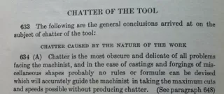
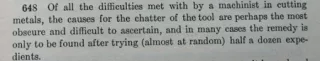
“Chatter is the most obscure and delicate of all problems facing the machinist –probably no rules or formulae can be devised which will accurately guide the machinist in taking maximum cuts and speeds possible without producing chatter.” (Taylor, 1907)
This quote is taken from F.W. Taylor’s book ‘On the Art of Cutting Metals’. Although the original book was unavailable to me at the time, I have since borrowed it from the University of Sheffield Library. Some passages from the book are shown in the images below:
He was absolutely correct; there were no formulae available to predict chatter vibrations. Fortunately, researchers were working on this important problem and in 1954 Prof. Jiri Tlusty from Prague was able to formulate the absolute stability limit for chip width for turning operations. That meant if the process planner selected a chip width smaller than this limit, the process would be stable and there would not be chatter vibrations irrespective of the spindle speed used.
Tlusty’s work was furthered by Prof S.A. Tobias in 1960. Tobias demonstrated the effect of spindle speed on the stability limit. Hence the stability lobe diagram emerged. The stability lobe diagram is a plot of cutting depth/chip width with respect to spindle speed. It gives us a boundary between stability and instability. The area below it is stable whereas the area above is unstable.
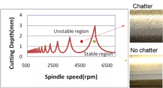
As you can see from the above figure, the red point is in the unstable area. If the spindle speed and cutting depth corresponding to this point is used in the process, the result will be chatter marks which deteriorate the surface quality. On the other hand, if the process planner selects the cutting depth and spindle speed corresponding to the green point, chatter vibrations can be avoided and a good surface finish can be obtained.
The stability lobe diagram was an important breakthrough because it was changing the perception of the machining community.
The stability lobe diagram was an important breakthrough because it was changing the perception of the machining community. Even today, higher speed is generally associated with higher vibrations. However, in case of chatter vibrations, this is not correct.
As shown in the stability lobe diagram used in our example, there are specific spindle speeds which result in higher stability and hence higher cutting depths are possible at those speeds. As a result, rather than decreasing the depth of cut and spindle speed to eliminate chatter, increasing the spindle speed and depth of cut may have the same effect. With this method, chatter vibrations are avoided and productivity is increased.
It took another 33 years for researchers to generate a stability lobe diagram for milling processes. Minis and Yanushevsky identified the stability lobe diagram numerically in milling in 1993. 2 years later, Altintas and Budak generated the stability lobe diagram for milling analytically in 1995.
Putting Theory Into Practice:
Chatter vibrations have continued to be an active research field since then. There have been many different methods developed to generate stability lobe diagrams including my own research that led to the formation of Productive Machines.
Productive Machines put these theories into practice to deliver insights into the machining process that can increase productivity and overcome process-induced problems.
Productive Machines put these theories into practice to deliver insights into the machining process that can increase productivity and overcome process-induced problems such as poor surface finish, low dimensional accuracy and instability caused by chatter vibrations.
One of Productive Machine’s unique solutions is the Stability Map. The Stability Map is a stability prediction tool similar to the stability lobe diagram; however it is computed across the entire tool path for a machined part rather than a single cutting condition. It is also able to predict stability of milling with complex cutting tool geometries. A heat map shows areas of stable conditions (white) and areas of unstable conditions (coloured) across the tool path with respect to the spindle speed choice. It can also be presented on the CAD model to highlight the problematic areas on the part.
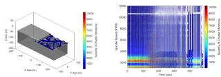
As depicted in the above figure, the stability of the entire milling operation is represented visually. The white areas between coloured areas (unstable conditions) represent the optimum choice of spindle speed to be employed for this milling operation. In this particular case for example, 10,600 rpm is the optimal spindle speed for mitigation of chatter vibration problems.
The fight against chatter is driven by the development of new processes, tools and materials for the manufacture of high value components.
The fight against chatter is driven by the development of new processes, tools and materials for the manufacture of high value components. Manufacturers are generally the first people to face chatter problems in this fight and they generally try to solve this problem using trial and error methodologies which leads to waste of resources such as energy, material and time.
Over a hundred years since F.W. Taylor first raised the issue, researchers are continuing to develop solutions against chatter vibrations. Productive Machines has taken the research results and commercialised a process enhancement service. Manufacturers are no longer alone dealing with chatter vibrations and they can benefit from this service to eliminate the trial and error processes, decrease the costs and waste and increase productivity and quality.