
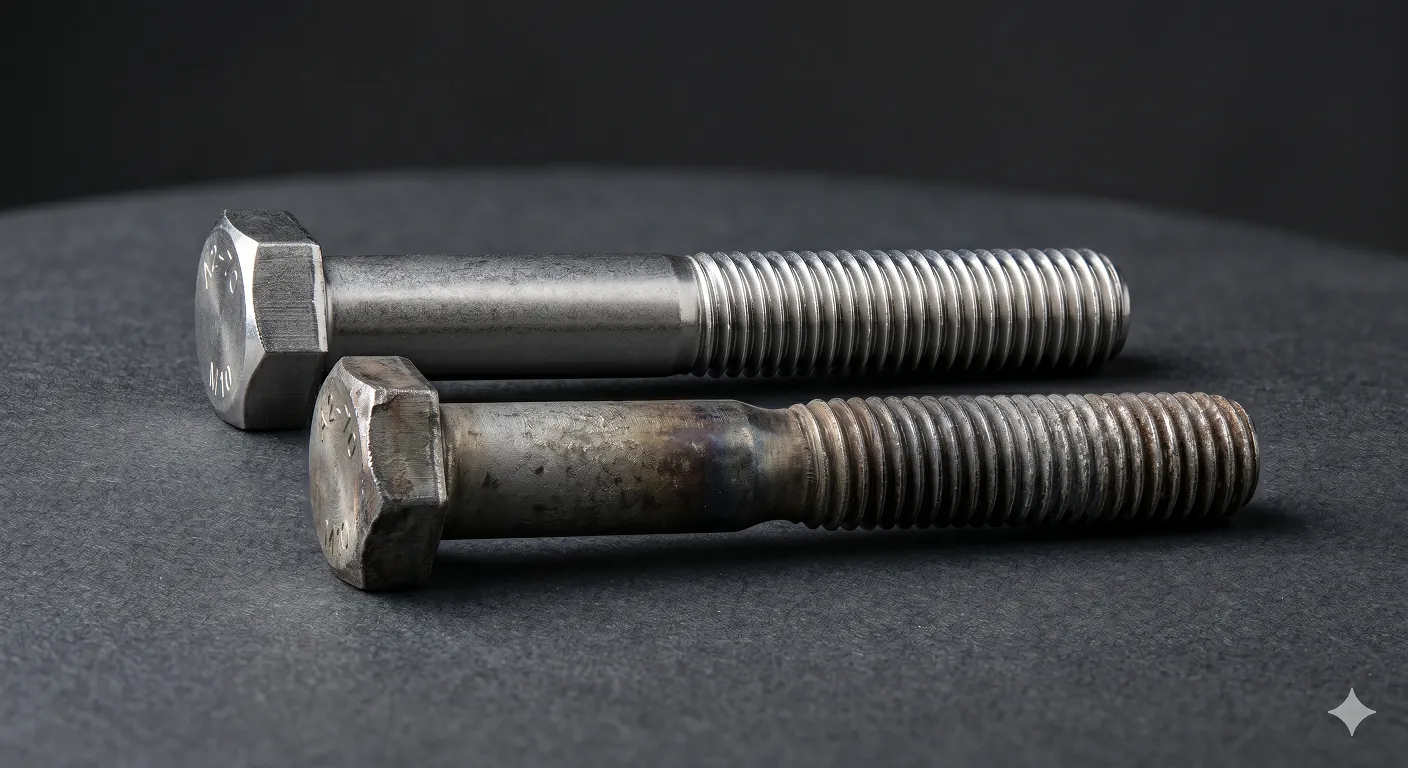
Patrick Faulkner, Lead Engineer at Accu, discusses the issue of creep in materials and what to watch out for when it comes to fasteners.
“Engineering depends on precision - tight tolerances, repeatable performance and components that are built to exacting specifications. Yet even with rigorous quality control, failures still occur over time, often with no obvious trigger. One of the most common causes is creep: a failure mode that works quietly, invisibly and over an extended period.
For anyone specifying fasteners, joining dissimilar materials, or designing assemblies for elevated temperatures or sustained loads, understanding creep isn't optional. It affects every material class - and getting it wrong produces failures that are notoriously hard to trace back to their root cause.
What is creep?
Creep is the slow, permanent deformation of a material under constant stress, below its yield strength and accelerated by elevated temperature. It differs from elastic deformation in one critical way - it doesn't recover when the load is removed. Once the material moves, it stays moved.
That's what makes creep so hazardous. A component can be specified correctly, installed properly and operating well within its rated capacity and still deform progressively until it fails. There's no single event to point to. Given enough time and the right conditions, creep will find a way through.
Two variables drive it: sustained mechanical stress and elevated temperature. Stress supplies the driving force; temperature supplies the atomic mobility that changes a material's internal structure over time. Critically, the two don't just work together - they amplify each other non-linearly. A process running slightly hotter than intended, or a component relocated a little closer to a heat source, can produce consequences wildly out of proportion to the change that caused them.
The three stages of creep
Creep doesn't progress at a steady rate. From first loading to eventual failure, a material moves through three distinct stages - each with its own mechanism and its own implications for how engineers should respond.
Primary creep starts with a high deformation rate that then slows down. As the material begins to deform, dislocations in the crystal structure pile up against grain boundaries and other obstacles, work-hardening the material against further movement. This is why new assemblies show early relaxation - a bolted joint settling after tightening, or a gasket bedding in under load. It's also why a re-torque schedule after first pressurisation exists - this behaviour is predictable and manageable.
Secondary creep, known as steady-state creep, is the long game. The rate stabilises at a low, roughly constant value as work-hardening and thermal recovery reach equilibrium. This stage dominates the service life of most components, sometimes for decades and it is the minimum creep rate measured here that engineers use to calculate remaining life. It is also highly sensitive to stress and temperature: a modest rise in either can multiply the creep rate several times over, sharply shortening the window before maintenance becomes critical.
Tertiary creep is the point of no return. The rate accelerates as internal voids form and merge along grain boundaries, the cross-section narrows and local stress rises even though the applied load hasn't changed. Left unaddressed, the result is creep rupture - failure under a load the component was originally able to carry. Warning signs include dimensional change accelerating after a long period of stability, surface cracking at stress concentrations and, in bolted assemblies, a sudden jump in preload loss after months or years of steady behaviour. Tertiary creep should be treated as urgent. Advice would be to reduce load immediately and assess its remaining life before returning the component to service.
Not just a high-temperature problem
Creep is closely associated with high-temperature applications, such as jet engines or chemical process reactors, but it is a mistake to think of it as exclusively a high-temperature phenomenon.
What matters isn't absolute temperature but what it is relative to the material's melting or softening point - its homologous temperature. Carbon steel becomes a meaningful creep concern at around 370–400°C. Aluminium's threshold drops to 100–190°C, which is well within reach of an automotive engine bay. For polymers, where the relevant benchmark is glass transition temperature rather than melting point, creep can begin at or below room temperature. Nylon and PTFE under sustained ambient load will creep slowly, but measurably and permanently.
Preload loss and bolt relaxation
In bolted joints, creep shows up primarily as stress relaxation and the distinction matters. When a bolt is tightened, it is placed under tension and the joint holds it at a fixed length, which means it cannot deform further. Over time, accelerated by temperature, the bolt's internal structure gradually adjusts to being stretched. The clamping force it exerts on the joint bleeds away - not because anything has broken, but because the material has quietly rearranged itself under sustained stress. The bolt stays the same length; the joint just isn't held as tightly.
The joints most at risk are high-temperature assemblies with creep-prone gaskets, joints using softer materials such as aluminium flanges, PTFE-faced gaskets or nylon washers and tapped holes in softer parent materials where thread flanks carry sustained bearing loads. In every case, risk scales directly with temperature and sustained stress.
The countermeasures for creep in fasteners are well established:
- Use hardened steel washers to distribute load and slow surface deformation.
- Choose all-metal locking mechanisms over nylon insert nuts for elevated-temperature or sustained-load applications - nylon loses its grip as it creeps.
- Apply a re-torque schedule. Initial gasket creep and bolt relaxation after first pressurisation are predictable and a planned re-torque afterward is good practice, not a sign of failure.
- Design for joint stiffness. Short, large-diameter bolts in rigid flanges with minimal soft elements in the load path lose a smaller proportion of preload than long, flexible assemblies for the same deformation.
Detecting creep before it becomes a problem
Creep rarely arrives without warning. Unlike brittle fracture, it leaves traces.
Baseline dimensional measurements taken at commissioning and repeated at defined intervals are the most practical monitoring tool. Stable dimensions mean predictable behaviour; an accelerating rate of change suggests the component has entered tertiary behaviour. Visual inspection should involve looking for elongation, surface cracking at grain boundaries and visible narrowing of cross-section. For bolted joints, the signs to look out for are fasteners that turn with less resistance than expected, uneven gasket compression or joints that begin to weep despite correct assembly, which all point to meaningful preload loss.
Where the project justifies it, ultrasonic testing can detect internal voids before they show on the surface and bonded strain gauges give a direct record of deformation over time. In power generation and process industry applications, replica metallography and the Larson-Miller parameter are established methods for estimating remaining life.
The response should match the stage of progress of the creep. Primary creep in a new assembly is expected; secondary creep in an established component is a managed situation requiring monitoring, tertiary creep is a stop-work condition until a proper remaining-life assessment is complete.
Design it out from the start
Most creep failures can be traced back to a design or specification decision made long before the component ever saw a load. The principles are straightforward -
For engineers specifying precision fasteners, the principles are straightforward - match the material to the service temperature using creep-specific data, rather than short-term tensile properties, reduce sustained stress through design wherever possible, control operating temperature and set inspection intervals with defined acceptance criteria before, not after, the first measurement is taken. Get these factors right for the actual service conditions and the fastener should perform indefinitely.”